MW Band Notch Filter
MW Band Notch Filter
This device is specifically designed for radio enthusiasts and operators who experience interference from strong local Medium Wave (MW) broadcast stations. Such interference can overload the Analog-to-Digital Converter (ADC), significantly degrading the reception quality of SDRs like the RX-888 and Web-888. By incorporating this MW Band Notch Filter into the RF front-end of your setup, you can effectively suppress strong MW broadcast signals, thereby protecting sensitive receivers and improving overall performance. This filter is particularly beneficial for Software-Defined Radios (SDRs), amateur radio transceivers, and High-Frequency (HF) receivers, ensuring optimal operation in environments with high levels of MW broadcast interference.
Design
This schematic represents a notch filter designed for the Medium Wave (MW) band, implemented using discrete LC components for RF signal suppression. The circuit is symmetrical and features a Pi-network-based band-stop filter topology, optimized to reject frequencies in the MW range (typically 530 kHz to 1700 kHz), while minimally affecting signals outside this band.
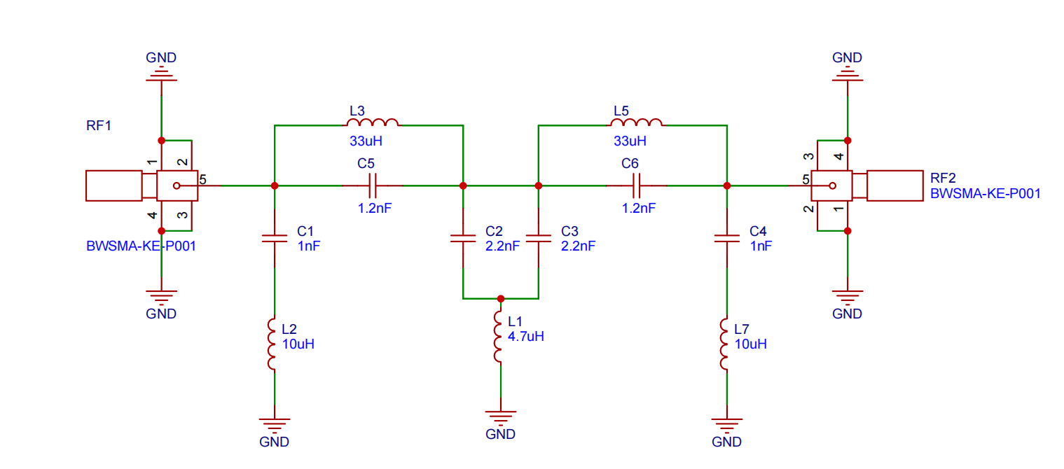
Circuit Components
Input/Output Interfaces: The RF input (RF1) and output (RF2) are connected via standard SMA connectors (BWSMA-KE-P001), providing robust RF interfaces for laboratory or field use.
Series LC Trap Networks: Two parallel resonant LC networks (C5–L3 and C6–L5), each consisting of a 33 µH inductor and a 1.2 nF capacitor, are connected in series between input and output. These networks are tuned to the center of the MW band and provide high impedance at resonance, thus attenuating MW signals.
Shunt Resonance Paths: The central section contains a dual capacitor pi-network (C2 and C3), with a central grounded inductor (L1, 4.7 µH), creating a band-stop response.
Additional shunt LC filters (C1–L2 and C4–L7) at the input and output further enhance the attenuation by forming additional notch characteristics.
Filtering Behavior: The configuration of alternating series and parallel LC elements forms a multi-stage notch filter that provides strong rejection at the desired MW frequencies.
The combination of resonant traps and pi-filter sections enables high rejection depth and increased bandwidth control.
Test Results
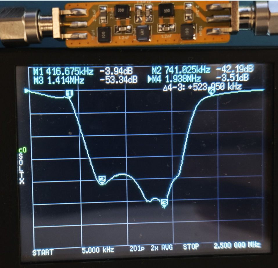
The performance of the MW Band Notch Filter was evaluated using the TinySA spectrum analyzer. The test results, as shown below, illustrate the frequency response of the filter. The graph highlights the effective attenuation of signals within the Medium Wave (MW) band, confirming the filter's ability to suppress strong local MW broadcast signals while maintaining minimal impact on frequencies outside the target range.
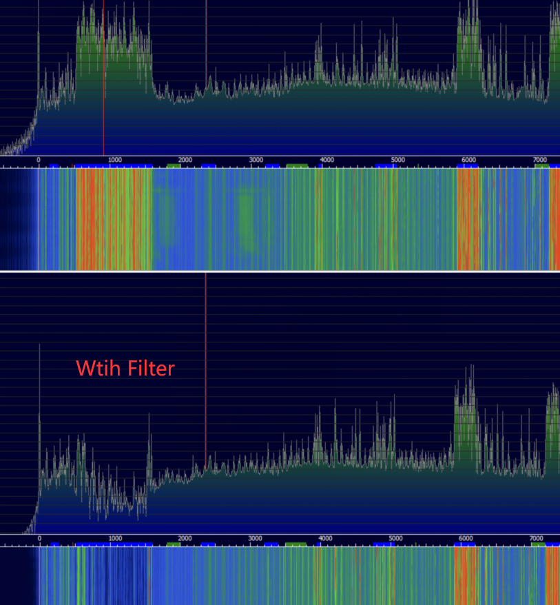
The application results, as displayed in HDSDR, clearly demonstrate the suppression of the entire MW band. This highlights the filter's effectiveness in mitigating interference from strong local MW broadcast signals, ensuring improved reception quality for SDRs and other sensitive receivers.
Bill of Materials
| ID | Quantity | Name | Package | Description |
|---|---|---|---|---|
| 1 | 2 | C1, C4 | C0805 | 1nF |
| 2 | 2 | C2, C3 | C0805 | 2.2nF |
| 3 | 2 | C5, C6 | C0805 | 1.2nF |
| 4 | 1 | L1 | IND-SMD_L2.9-W2.8 | 4.7µH |
| 5 | 2 | L2, L7 | IND-SMD_L2.9-W2.8 | 10µH |
| 6 | 2 | L3, L5 | IND-SMD_L2.9-W2.8 | 33µH |
| 7 | 2 | RF1, RF2 | SMA-SMD_BWSMA-KE-P001 | SMA Connectors |
Gerber Files
Tips
For instructions on how to use Gerber files to order PCBs from JLCPCB, please refer to the document here: Instruction